


In this the second part of the three-part series, Cindo Alves discusses the basics of designing fibre-optic systems.
One of the most important considerations in designing a fibre-optic system is the optical loss budget, making sure a proper amount of signal reaches the receiver to ensure proper operation. However, several other factors need to be taken into consideration. This article concentrates on basic design concepts to give a clear idea of how fibre-optic systems are built.
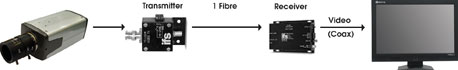
You need more than just optical fibre to make a communications system. Using fibre-optic transmission equipment, any signal, whether it is video, audio or data can be modulated onto light that carries the signal through the glass core of the fibre. A fibre-optic system is primarily composed of three components, although the specifications for each will vary depending on the application. The components are common in every fibre-optic communication system. These are:
* Transmitter – A transmitter uses an electronic signal input to modulate a light source or emitter within the transmitter.
* Fibre-optic cable – The light is then transmitted through an optical fibre cable. There is a multitude of fibre-optic cables for varying environments.
* Receiver – The receiver uses an optical detector that then receives the modulated light and converts it back to an electrical signal.
Optical transmitters
Several factors determine the performance of a fibre-optic transmitter, including the modulation method, the type of light source, the operating wavelength, and the optical power.
* Analogue vs. digital – Some transmitters use analogue waveforms and others operate with discrete digital pulses. Analogue is commonly used as it is inexpensive; however, analogue transmission can become non-linear or distorted. Digital, on the other hand, is more tolerant of noise and distortion.
* Light source – For single-mode fibres, which have a small core, the best match is a transmitter that uses a laser diode (LD) or surface emitting diode, which emits light from an area measuring only a few micrometres. Transmitters that use light emitting diodes (LEDs), which have a larger emitting area, work well with multimode fibres.
* Wavelength – The wavelength used by the optical emitter in the transmitter also affects the systems performance. One example is signal attenuation. The longer the wavelength used by the optical emitter, the less the attenuation. However, there is a trade-off in equipment cost.
* Output power – The light launched or delivered to the fibre must be sufficient to overcome the losses in the fibre-optic cabling system so that sufficient optical power is available for the receiver to detect.
Fibre-optic cable
The optical fibre or fibres are housed in a cable to simplify handling and protect them from environmental stresses. Fibres must be precisely aligned with light sources to collect their output efficiently. Likewise, if light is transferred between fibres, the two ends must be precisely aligned. Because their diameters are very small, mechanical tolerances for proper alignment are tight. Consequently, much more attention must be paid to connectors and splices than in electrical communication over wires. It should be noted that the maximum transmission range of a system is much more dependent on losses in the fibre than on the power of the transmitter (source) or the sensitivity of the receiver (detector).
Optical receivers
Several factors determine the performance of a fibre-optic receiver, including a receiver’s sensitivity, dynamic range, and the detector type used.
* Sensitivity – Sensitivity measures how well a receiver responds to a signal as a function of its intensity. Several factors affect a receiver’s sensitivity including signal quality, optical wavelength, type of detector used and the quality of the amplification circuit.
* Dynamic range – Input signals must be within a detector’s dynamic range, the range of input power over which the receiver produces the desired output, in order to avoid distortion.
* Detector type – The PIN diode is the most common type of diode used. They are relatively inexpensive and do not require great amounts of power, but are limited in sensitivity. Avalanche diodes may be used for increased sensitivity and faster transmission for longer distance applications, however, they cost more.
System design objectives
Now that the three general components of a fibre-optic system have been reviewed, it is time to review how systems are designed. When designing any fibre optic transmission system, whether video, audio or data communications, there are several objectives that need to be kept in the forefront of the designer’s mind.
* Provide a cost-effective system.
* Maximise the optical capabilities of the fibre.
* Minimise light loss (attenuation) in the fibre.
* Maximise reliability.
* Facilitate maintenance of the system.
* Provide for future upgrades and changes in the system.
These objectives will be addressed and considered as you review various concepts and design practices.
Initial design process
During the walkthrough it is imperative to develop a good understanding of your customer’s infrastructure and the out-of-plant environment of the project in order to determine how it will affect the overall design and layout of the system.
1. Locate and/or identify field device locations:
* CCTV cameras.
* Access control panels.
* Intercom stations.
2. Identify existing utilities location:
* Entrance facilities.
* Wiring closets.
* Power.
3. Environmental constraints:
* Temperature.
* Humidity.
* EMI/RFI interference.
4. Describe proposed cable routing:
* Define topology.
* Determine distance between equipment (ie, cable lengths).
* Determine fibre count needed for each cable run – 50% spare is a good rule of thumb.
* Cable access for maintenance and repair.
* Cable construction suitable for the installed environment (ie, indoor/outdoor; conduit/trays).
* NEC compliance.
5. Adherence to codes and ordinances:
* Local building code.
* Acquire proper permits.
Four steps in system design
There are four steps in designing the optical portion of the system that every design professional needs to understand and be capable of performing.
1. Define the operational parameters of the system.
2. Define the cabling plant requirements and calculate the optical path loss.
3. Select the appropriate transmission equipment that meets the operational requirements and the optical power budget for the system.
4. Review the optical loss budget and allow for an appropriate safety margin for the system.
For more information contact Cindo Alves, Alves Audio Visual Services, +27 (0)82 414 2146, [email protected]


© Technews Publishing (Pty) Ltd. | All Rights Reserved.
 printer friendly version