


Ref: z2717157m
This two part article was provided by representative for Contemporary Controls in South Africa, Electronic Products Design. Written by Paula Doyle, a doctoral researcher with the Circuits and Systems Research Centre at the University of Limerick in Ireland, Introduction to realtime Ethernet covers an introduction to realtime systems and a study of Ethernet's potential as a realtime network. The second part provides a study of the realtime industrial Ethernet solutions available today.
Paula Doyle has a first class honours B. Engineering degree in Computer Engineering and her research interests include embedded realtime systems, with emphasis on control networks for smart transducers with applications in the field of industrial automation. Ms Doyle's Ph.D. interest is based on the time-triggered transducer clusters in an Ethernet networking environment.
Introduction
Realtime electronic distributed control systems are an important development of the technological evolution. Electronics are employed to control and monitor most safety-critical applications from flight decks to hospital operating rooms. As these realtime systems become increasingly prevalent and advanced, so does the demand to physically distribute the control in strict realtime. Thus, there is a need for control network protocols to support stringent realtime requirements. Realtime networks must provide a guarantee of service so they will consistently operate deterministically and correctly.
Ethernet, as defined in IEEE 802.3, is non-deterministic and thus, is unsuitable for hard realtime applications. The media access control protocol, CSMA/CD with its backoff algorithm, prevents the network from supporting hard realtime communication due to its random delays and potential transmission failures.
Decreasing costs and increasing demand for a single network type, from boardroom to plant-floor, have led to the development of industrial Ethernet. The desire to incorporate a realtime element into this increasingly popular single-network solution has led to the development of different realtime industrial Ethernet strategies. Fieldbus networking standards have failed to deliver an integrated solution. Typically, emerging realtime industrial Ethernet solutions complement the fieldbus standards - for example, by using common user layers. This article covers an introduction to realtime systems and a study of Ethernet's potential as a realtime network. Part 2 provides a study of the realtime industrial Ethernet solutions available today.
Realtime introduction
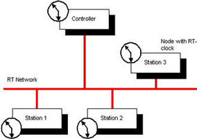
Realtime (RT) systems are becoming increasingly important, as industries focus on distributed computing in automation, see Figure 1. As computing costs decrease, and computing power increases, industry has relied more on distributed computers to deliver efficiency and increased yield to production lines. RT does not automatically mean faster execution, but rather that a process is dependent on the progression of time for valid execution.
RT systems are those that depend not solely on the validity of data but also on its timeliness. A correct RT system will guarantee successful system operation - so far as its timely execution is concerned. RT systems are generally broken into two main sub-categories: hard and soft.
Hard realtime (HRT) systems are those in which incorrect operation can lead to catastrophic events. Errors in HRT systems can cause accidents or even death, such as in flight control or train control.
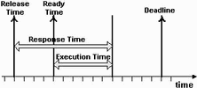
Soft realtime (SRT) systems, on the other hand, are not as brittle. An error in a SRT system, while not encouraged, will not cause loss of property or life. SRT systems are not as safety-critical as HRT systems, and should not be employed in a safety-critical situation. Examples of SRT systems are online reservation systems and streaming multimedia applications where occasional delays are inconvenient but not serious. Jobs are the RT system's building blocks. Each RT job has certain temporal quantities (Figure 2):
1. Release time.
2. Ready time.
3. Execution time.
4. Response time.
5. Deadline.
Release time of a job is when a job becomes available to the system. Execution time is the time for a job to be completely processed. Response time is the interval between release time and completion of the execution. Ready time is the earliest time a job can start executing (never less than the release time). The deadline is the time by which execution must be finished, beyond which the job is late. A deadline can be either hard or soft, indicating the job's temporal dependence. As mentioned earlier, a missed hard deadline can have serious consequences. All RT systems have a certain level of jitter (a variance on actual timing). In a RT system, jitter should be measurable so system performance can be guaranteed.
To develop an RT distributed system of interconnected computers, it is vital to provide communication among the various computers in a reliable and timely fashion. Distributed processors running RT applications must be able to intercommunicate via a RT protocol, otherwise the temporal quality of work is lost. Realtime communication networks are like any RT system. They can be hard or soft, depending on requirements and their 'jobs' include message transmission, propagation, and reception. A number of RT control networks are employed in industry, but none have the popularity or bandwidth of Ethernet.
The demand for realtime Ethernet
Demand for Ethernet as an RT control network is increasing as manufacturers realise the benefits of employing a single network technology from boardroom to plant floor. Decreased product costs plus the possibility of overlapping training and maintenance costs for information, field level, control and possibly device networks would greatly reduce manufacturers' expense.
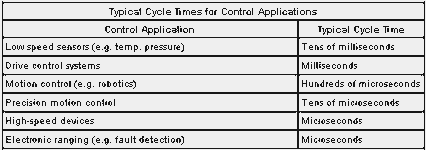
At the RT control level, Ethernet offers many benefits over existing solutions. As a control network, 10 Gbps Ethernet offers bandwidth almost 1000x faster than today's comparable fieldbus networks (such as the 12 Mbps of ProfiBus) and can also support RT communication. Distributed applications in control environments require tight synchronisation so to guarantee the delivery of control messages within defined message cycle times (typical times appear in Table 1). Traditional Ethernet and fieldbus systems cannot meet cycle time requirements below a few milliseconds, but emerging RT industrial Ethernet solutions allow cycle times of a few microseconds.
Along with the increased bandwidth and tight synchronisation, RT Ethernet gives manufacturers the security of using a physical and data-link layer technology that has been standardised by both the IEEE and the ISO. Ethernet can provide reduced complexity with all the attributes required of a field, control or device network - in operations having up to 30 different networks installed at this level. Furthermore, Ethernet devices can also support TCP/IP stacks so that Ethernet can easily gate to the Internet. This feature is attractive to users since it allows remote diagnostics, control, and observation of their plant network from any Internet-connected device around the world with a license-free web browser. Although Ethernet does introduce overhead through its minimum message data size (46 bytes), which is large in comparison to existing control network standards, its increased bandwidth, standardisation and integration with existing plant technology should generate good reasons to consider Ethernet as a control network solution.
Ethernet and CSMA/CD
Ethernet, as defined in IEEE 802.3, is unsuitable for strict RT industrial applications because its communication is non-deterministic. This is due to the definition of its media access control (MAC) protocol, based on carrier sense multiple access/collision detection (CSMA/CD). The implementation described in the standard uses a truncated binary exponential backoff algorithm.
With CSMA/CD, each node can detect if another node is transmitting on the medium (carrier sense). When a node detects a carrier, its carrier sense is turned on and it will defer transmission until determining the medium is free. If two nodes transmit simultaneously (multiple access), a collision occurs and all frames are destroyed. Nodes detect collisions (collision detection) by monitoring the collision detect signal provided by the physical layer. When a collision occurs, the node transmits a jam sequence.
When a node begins transmission there is a time interval, called the collision window, during which a collision can occur. This window is large enough to allow the signal to propagate around the entire network/segment. When this window is over, all (functioning) nodes should have their carrier sense on, and so would not attempt to commence transmission.
When a collision occurs, the truncated binary exponential backoff algorithm is employed at each 'colliding' node. The algorithm works as follows:
Initially: n:=0, k:=0, r:=0.
When a collision occurs, the node enters the algorithm which states:
* It increments n, the transmit counter, which tracks the number of sequential collisions experienced by a node.
* If n>, (16 unsuccessful successive transmission attempts), transmission fails and the higher layers should be informed.
* If n< = 16, select a number from the set k = min (n,10) (truncation).
* A random number, r, is selected from the set (0, 1,2,4...2 k) (exponential and binary).
* The node then waits r x slot_time before recommencing a transmission attempt.
One advantage of this backoff algorithm is that it controls the medium load. If the medium is heavily loaded, the likelihood of collisions increases, and the algorithm increases the interval from which the random delay time is chosen. This should lighten the load and reduce further collisions.
Ethernet introduces the possibility of complete transmission failure and the possibility of random transmission time, hence IEEE 802.3's non-determinism and unsuitability for RT communications - especially on heavily-loaded networks. Re-definition of the media access protocol could solve the problem but would leave the new nodes unable to interoperate with legacy Ethernet nodes.
Ethernet is non-deterministic only if collisions can occur. To implement a completely deterministic Ethernet, all collisions must be avoided. A collision domain is a CSMA/CD segment where simultaneous transmissions can produce a collision and where collision probability increases with the number of nodes transmitting. Completely avoiding collisions, therefore, gives Ethernet - with a relatively large bandwidth and popularity - an opportunity to be developed for the RT domain. The most common way of implementing a collision-free Ethernet is through the use of hardware.
A situation where two or more nodes compete for medium access to a network segment is called shared Ethernet.
Full and half duplex Ethernet
When Ethernet was standardised in 1985, all communication was half duplex. Half duplex restricts a node to either transmit or receive at a time but not to perform both actions concurrently.
Nodes sharing a half duplex connection are in the same collision domain. This means these nodes will compete for bus access, and their frames may collide with other frames on the network. Unless access to the bus is controlled at a higher level and highly synchronised across all nodes on the collision domain, collisions can occur and RT communication is not guaranteed.
Full duplex communication was standardised for Ethernet in the 1997 edition of 802.3 as IEEE 802.3x. With full duplex, a node can transmit and receive simultaneously, but only two devices can be connected on a single full duplex link - typically a node-to-switch or switch-to-switch configuration. Theoretically, full duplex links can double available network bandwidth from 10 to 20 Mbps or 100 to 200 Mbps, but in practice it is limited by the internal processing capability of each node. Full duplex provides every node with a unique collision domain - completely avoiding collisions and even ignoring the traditional CSMA/CD protocol.
Since full duplex links have a maximum of two nodes per link, such technology is not viable as an industrial RT solution without the use of fast, intelligent switches that can form a network with single collision domains for each node-ie, switched Ethernet.
Full duplex, switched Ethernet
With shared Ethernet, nodes compete for access to the media in their shared collision domains. The use of a non-deterministic bus access scheme, such as CSMA/CD, makes shared Ethernet unviable as a RT network solution. The most popular method of collision-avoidance, which produces a deterministic Ethernet, introduces single collision domains for each node guaranteeing the node exclusive use of the medium and eliminating access contention. This is achieved by implementing full duplex links and hardware devices such as switches and bridges. These devices can isolate collision domains through the segmentation of the network because each device port is configured as a single collision domain. Although, both switches and bridges will suffice, switches are more flexible because they allow more segments.
Switches
Switches are data-link layer hardware devices that permit single-collision domains through network segmentation. While a bridge operates like a switch, it only contains two ports compared to switches that have more than two - with each port connected to a collision domain. Switches can operate in half duplex or full duplex mode. When full duplex switches are used with full duplex capable nodes, no segment will have collisions. Today's switches are more intelligent and faster and with careful design and implementation could be used to achieve a hard RT communication network using IEEE 802.3.
Although switches are data-link layer devices, they can perform switching functions based on data from layers 3 and 4. Layer 3 switches can operate on information provided by IP - such as IP version, source/destination address or type of service. Layer 4 devices can switch by source/destination port or even information from the higher-level application.
Further refinements to the IEEE 802 standards, specifically for switch operations, are 802.1p and 802.1Q. IEEE 802.1p (incorporated into IEEE 802.1D) brings quality of service (QoS) to the MAC level and defines how these switches deal with prioritisation-priority determination, queue management, etc. This is achieved by adding a 3-bit priority field to the MAC header, giving 8 (0-7) different priority levels for use by switches or hubs. As defined, 802.1p supports priorities on topologies compatible with its prioritisation service, but for Ethernet, which has no prioritisation field in its frame format, it uses 802.1Q.
IEEE 802.1Q defines an architecture for virtual bridged LANs, their services and the protocols and algorithms used by those services. 802.1Q allows Ethernet frames to support VLANs (virtual local area networks) - limiting broadcast domains and thereby reducing broadcast traffic on the entire LAN. This is achieved by inserting 4 bytes between the source address and length/type fields in the frame header, which among other identifiers, includes that of the originating VLAN.
For an RT industrial Ethernet application, an 802.1p/Q implementation has certain advantages: it introduces standardised prioritisation, allowing control engineers up to eight different user-defined priority levels for their traffic. But these standards also have drawbacks including the extra hardware costs for the increased frame length (1522 bytes) - which introduces compatibility issues with legacy Ethernet networks. An RT implementation using 802.1 p/Q requires full duplex, switched Ethernet. IEEE 802.1p/Q are acceptable for certain applications of RT Ethernet in industry when switch 'through' time is predictable and an overload situation will not result in hard deadlines being missed.
Although switches can certainly provide RT deterministic Ethernet communication and are the backbone of the industrial Ethernet solutions available today, they have drawbacks. They are costly - a major influence on cost-conscious industries. They are powered devices capable of failure (a major factor for hard RT control operations). And sometimes the operational predictability is not guaranteed by the manufacturer.
TCP/UDP/IP for realtime Ethernet
With industrial Ethernet, the trend is to define an application-layer environment along with the TCP/IP protocol, to realise an industrial automation networking solution. Some RT Ethernet solutions (eg, EtherNet/IP) perform all their communication, RT included, through the TCP/UDP/IP stack. But most solutions, while providing TCP/IP compatibility, do not employ this protocol for RT communication. In a system like EtherNet/IP, TCP is used for initialisation and configuration of explicit messages while UDP, with its reduced overhead, is used for RT I/O (implicit messaging).
Typically, RT industrial Ethernet applications are compatible with TCP/IP, but the protocol suite is bypassed for all RT communication. The ability of an RT Ethernet solution to intercommunicate with an office-based system is paramount to achieve the Ethernet technology plant of the future.
Conclusion
This first part of the article covered a broad introduction to Ethernet for RT. It described concepts to be developed in the follow-up article: Realtime Ethernet II. Part of the article provides detail on existing RT Ethernet solutions such as PROFInet V3, ETHERNET Powerlink and EtherNet/IP plus IEEE 1588 - an important supporting technology for clock synchronisation.
Introduction to realtime Ethernet II
In realtime Ethernet I, we introduced the basic concepts of Ethernet's capacity to deliver a realtime (RT) communication system. Realtime Ethernet II introduces some of the RT solutions available to industry today: PROFInet, EtherCAT and ETHERNET Powerlink. It also provides an introduction to a single standard, IEEE 1588 that is growing in popularity amongst RT Ethernet developers to provide sub-microsecond synchronisation accuracy of distributed clocks over Ethernet.
IEEE 1588
IEEE 1588 specifies 'A protocol to synchronise independent clocks running on separate nodes of a distributed measurement or control system to a high accuracy and precision.' IEEE 1588 is, or will be, incorporated into EtherNet/IP, ETHERNET Powerlink, EtherCAT and PROFInet - making it a popular standard for delivering RT over Ethernet.
In IEEE 1588, all network nodes down to the transducer level contain an IEEE 1588 clock, synchronised with all network peers (see Figure 3) using Precision Time Protocol (PTP). At device level, sensors can timestamp their data locally and actuators can operate at a precise time, avoiding stack and application delays between transducer and controller. The accuracy of the system depends on the synchronisation of local RT clocks.
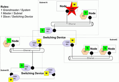
IEEE 1588 defines two separate types of clocks: ordinary and boundary. Boundary clocks (BC) are employed in devices such as hubs or switches - where more than one PTP communication path (port) exists. Ordinary clocks exist in devices having a single port - eg, normal network devices. Each BC port can act as a master or ordinary clock in its own segment.
PTP is for networks that support multicasting but keep multicasts within a subnet and where each local clock fulfils exacting requirements. The grandmaster clock (GMC) is the best clock in the system - with the best inherent stability, accuracy, resolution, etc. defined by the standard. The Best Master Clock algorithm (BMC), run by every live node, determines clock quality. Within each subnet, the BMC determines the master clock; in a single-subnet system the master is the GMC.
The GMC determines system synchronisation; system clocks synchronise their subnet clocks to the system. There is only one GMC per system, and only one master clock per subnet.
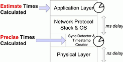
Synchronisation is performed as follows. All masters periodically broadcast 'sync' messages containing an estimate of the time the message will physically leave the master. The precise receipt time of these messages is noted at the slaves. The precise sending time of the message is noted at the grandmaster. All precise timing measurements are performed as close to the physical layer as possible - to eliminate the delays from the network stack and operating system - while the estimated times are calculated by the IEEE 1588 code at the application layer (see Figure 4). Following the sync message, the master transmits a related 'follow_up' message containing the precise sending time of the sync message. A slave uses the transmission and reception times to calculate its offset and can initiate synchronisation with the delay measurement, which is not periodic and not performed as often as the protocol synchronisation. Sync messages do not propagate beyond their originating subnet.
The resolution of the system clock is the resolution of the GMC. If required, the GMC can be synchronised to an external source such as GPS.
IEEE 1588 is a highly precise system for synchronising distributed nodes for applications such as motion control and robotics. It was designed for multicasting networks but with the popularity of industrial Ethernet, Annex D was included for an Ethernet implementation of PTP. Although IEEE 1588 does not alter Ethernet or make it more deterministic or reliable, it does provide a method for other protocols to do so. A highly synchronised system of distributed nodes - coupled with an application for handling resolution and controlling traffic - could deliver hard, deterministic RT over Ethernet.
PROFInet
PROFInet is a plant-wide fieldbus standard for distributed automation systems. It uses object-orientation and available IT standards (TCP/IP, Ethernet, XML, COM). PROFInet is also built on IEEE 802.3 and is interoperable with TCP/IP-allowing it to be implemented on existing Ethernets. It is compatible with PROFIBUS-DP.
PROFInet V1, has a response time of 10-100 ms. PROFInet-SRT (soft realtime) allowed PROFInet to work with a factory automation cycle time of 5-10 ms, achieving RT solely in software. It uses TCP/IP and a dedicated software channel for RT communications. PROFInet-IRT brings a hard-RT element to the PROFInet protocols. The three PROFInet protocols allow differing degrees of RT. PROFInet for hard RT is PROFInet-IRT.
PROFInet-IRT
PROFInet IRT (isochronous RT) was developed for systems requiring sub-microsecond synchronisation, typically high-performance motion control systems. The benchmark for such a system is 1 ms cycle time, 1 µs jitter accuracy, and guaranteed determinism - which IRT fulfils.
Since software introduces jitter above 1 µs, IRT (unlike SRT) is a hardware solution with highly synchronised Ethernet nodes. Using full-duplex switched fast Ethernet, it divides the communication cycle into a standard TCP/IP open channel and a deterministic RT channel. The channel ratio is system-dependent and is chosen by the systems engineer.
Each PROFInet-IRT device has a special ASIC (application-specific integrated circuit) for handling node synchronisation and cycle subdivision and incorporates an intelligent 2 or 4 port switch.
The PROFInet switch in every node is highly synchronised, contains a schedule of bus access and can deal with RT and non-RT traffic. It prioritises RT traffic and provides full-duplex links for all ports. Contemporary switches (even cut-through) add jitter that would impact on determinism. PROFInet switches minimise jitter to where it has a negligible effect. The PROFInet communication model allows both RT and non-RT traffic to co-exist on one network without additional precautions.
By 2005, PROFInet-IRT and SRT will incorporate PROFISafe, the PROFIbus safety solution for manufacturing and processing industries.
PROFInet, of all the solutions discussed here offers the greatest determinism - and since this is built into the PROFInet-IRT device, the systems engineer is spared from the burden of configuration to guarantee RT communication.
EtherCAT
EtherCAT (Ethernet for control automation technology) is the motion-control RT solution from Beckhoff. It can process 1000 I/Os in 30 µs, but requires full-duplex. It can use copper or fibre-optic cables. EtherCAT is based on the master/slave principal and can interoperate with normal TCP/IP-based networks and other Ethernet-based solutions such as PROFInet. It also supports any Ethernet topology, including the bus.
The EtherCAT master processes RT data via dedicated hardware and software (Beckhoff currently uses its PC-based TwinCAT OS and TwinCAT Y driver). In the future, further variations will be introduced that will also provide the same guarantees. The current master prioritises EtherCAT frames over normal Ethernet traffic, which is transmitted in gaps. The master controls traffic by initiating all transmissions.
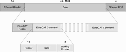
The telegrams are standard Ethernet, and the data field encapsulates the EtherCAT frame (an EtherCAT header and one or more EtherCAT commands). Each command contains a header, data and working counter (WC) field. Each Ethernet telegram can contain many EtherCAT commands - realising a higher bandwidth and more efficient use of the large Ethernet data field size and header (see Figure 5). The standard Ethernet CRC is used to verify message correctness.
The EtherCAT master fully controls its slaves. Its commands only elicit responses; slaves do not initiate transmissions. The two EtherCAT communication methods used are 'Ether type' or UDP/IP encapsulation.
The 'Ether type' uses the type field (defined in Ethernet II), which is more commonly known as the length field in IEEE 802.3. The Ether Type implementation does not use IP, thus limiting EtherCAT traffic to the originating subnet. Encapsulating commands using UDP/IP allows EtherCAT frames to traverse subnets, but has drawbacks. The UDP/IP header adds 28 (20: IP, 8: UDP) bytes to the Ethernet frame and undermines RT performance through its non-deterministic stack. EtherCAT slaves range from intelligent nodes to 2-bit I/O modules and are networked via 100Base-TX, fibre-optic cable or E-bus (depending on distance requirements). E-bus is an EtherCAT physical layer for Ethernet offering a LVDS (low-voltage differential signal) scheme. Slaves are hot pluggable in any topology of branches or stubs. Multiple 'slave rings' can exist on a single network if connected by a switch.
EtherCAT slaves have integrated memory from 2 bits to 64 Kbytes. They appear to the Ethernet as a single device though actually comprising up to 65,535 devices. They are configured in an open-ring topology, with the Ethernet interface at the open end. Masters transmit commands to the MAC address of the first device. When the signal reaches the Ethernet/slave interface, it is converted to E-bus specifications (if E-bus is employed) and forwarded.
A slave receives a telegram, processes it (in hardware) then forwards it to the next slave on the ring. This processing delays the telegram by an order of nanoseconds. The last slave returns the completed telegram, via the ring, to the master. On the return route, each slave amplifies and regenerates the signal. Each slave has two Tx and Rx interfaces, so bi-directional communication occurs without contention.
In each EtherCAT command, the WC increments when a slave processes a command addressed to it, allowing the master to determine if each addressed slave is exchanging data, although correct data is not guaranteed.
The FMMU (field memory management unit) of each configurable slave converts a logical address to a physical one, and that information is available to the master at initialisation. Thus, each slave needs a special ASIC. On telegram reception, a slave determines if it is addressed and then passes data to/from the telegram - incurring a delay of some nanoseconds. EtherCAT is also internally synchronised by a distributed clock algorithm (a simplified version of IEEE 1588) although external synchronisation is achievable with IEEE 1588.
EtherCAT is a fast RT Ethernet solution and deterministic if not used with UDP/IP or intermediate switches or routers between master and slaves.
Ethernet Powerlink (EPL)
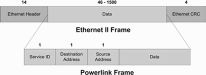
EPL is a hard-RT protocol based on fast Ethernet. Like EtherCAT, it uses the Ethernet II Frame type field. EPL devices use standard Ethernet hardware with no special ASICs. EPL can deliver a cycle time of 200 1 µs with jitter under 1 μs. Its frame is encapsulated as illustrated in Figure 6.
EPL uses cyclic communication with time-slot division and the master/slave model. One master (manager) is allowed per network. The master schedules all transmissions and is the only active station - slaves transmitting on request.
The four EPL cycle subdivisions are illustrated in Figure 7.
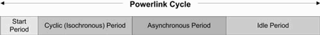
During the start period, the EPL master broadcasts the 'start-of-cyclic' (SoC) frame which synchronises the slaves. The timing of this frame provides the only time base for the network synchronisation: all other frames are purely event-driven.
After transmitting the SoC frame, the cyclic period occurs as the manager polls each station with a 'poll request' frame. Only then does the slave respond with a 'poll response' frame containing data - hence, collisions are avoided. The slave broadcasts its response to all devices; thus, inter-slave communication can occur.
After successful polling of all slaves, the master broadcasts the 'end-of-cyclic' (EoC) frame, informing each slave that the cyclic traffic progressed correctly.
The asynchronous period allows non-cyclic data transfers under master control. To transmit during this period, a slave must have informed the master in its 'poll response' during the cyclic period. The master builds a list of waiting slaves and employs a scheduler to guarantee that no send request will be delayed indefinitely. During the asynchronous period, standard IP datagrams can be transferred.
Unlike PROFInet, EPL does not employ switches to avoid collisions or to provide the network synchronisation; the master controls this. EPL networks can be built with standard hubs - it is proposed that each device incorporate a hub for ease of bus implementation. Switches, although not prohibited, are not recommended for EPL because they add jitter and reduce determinism. Since the EPL network avoids collisions via time-controlled bus access, up to 10 hubs can be cascaded (an allowable exception to the 5-4-3 Ethernet rule).
Currently, EPL devices demanding RT communication cannot co-exist on the same segment as non-RT Ethernet devices. However, EPL devices can operate as normal Ethernet devices. In protected mode, the RT segment must be separated from normal traffic by a bridge or router. In open mode, RT traffic shares the segment with normal traffic, but RT communication is compromised. In the next Powerlink version (V3), IEEE 1588 will be used to synchronise traffic across multiple RT segments - providing a more distributed EPL implementation, but true RT segments will still contain only EPL devices. Unlike PROFInet where normal Ethernet and RT devices can co-exist and not affect RT traffic, EPL must be protected from non-RT communication through bridges or routers. Unlike PROFInet or EtherCAT, which need special ASICs, EPL employs standard Ethernet hardware.
Conclusion
Realtime Ethernet is a fast-growing, exciting development of the Ethernet protocol. The ability to have RT control segments running on the same network as office applications brings many new possibilities for industrial applications. With different protocols offering different levels of RT service, it is vital to understand the RT requirement of the system before choosing a solution. Sub-microsecond synchronisation accuracy, with IEEE 1588, along with an RT protocol, can provide an Ethernet capable of delivering hard, fast and deterministic RT for applications such as motion control, while other solutions cater for softer applications. Therefore, when choosing RT Ethernet, it is vital to consider the realtime, interoperability and flexibility requirements of your system along with all possible solutions before making a commitment.
For more information contact Jaap Willemse, Electronic Products Design, 012 665 9700.
| Tel: | +27 12 493 0852 |
| Email: | [email protected] |
| www: | www.epd.co.za |
| Articles: | More information and articles about Electronic Products Design |


© Technews Publishing (Pty) Ltd | All Rights Reserved
 printer friendly version